Lab 7: The Advanced Encryption Standard
Introduction
This lab dives into the Advanced Encryption Standard (AES) for secure communication. The initiates plain text communication between the STM32L432KCU microcontroller unit and the iCE40UP5K FPGA. The MCU initiates SPI communication with the FPGA, which behaves as the accelerator, providing it with an encryption key and unsecure message. Once the 128-bit message undergoes sufficient AES cycling, the encrypted message is sent back to the MCU.
Design and Testing
The Advanced Encryption Standard requires five fundamental sub-modules: SubBytes, ShiftRows, MixColumns, AddRoundKey, and KeyExpansion. The SubBytes module employs a synchronous sbox function, which converts the message bits to their counterparts outlined in the table in FIPS 197 Figure 7. A synchronous method is employed here to preserve the LUTs onboard the FPGA to ensure physical implementation is possible. A similar rational motivates the KeyExpansion module which systematically generates a new key for the subsequent round based on the current key and round number. Following AES standards, the 128-bit encryption process follows eleven cycles: the first passes the plaintext message into the AddRoundKey function and generates a new key, the second through tenth cycle passes the increasingly encrypted method through the SubBytes, ShiftRows, MixColumns, AddRoundKey, and KeyExpansion modules (in that order), and the last cycle mimics the primary cycle, only bypassing the MixColumns function. These cycles were implemented with a Finite State Machine, governing when modules are active, the current round, and which modules to skip.
Technical Documentation
Block Diagram
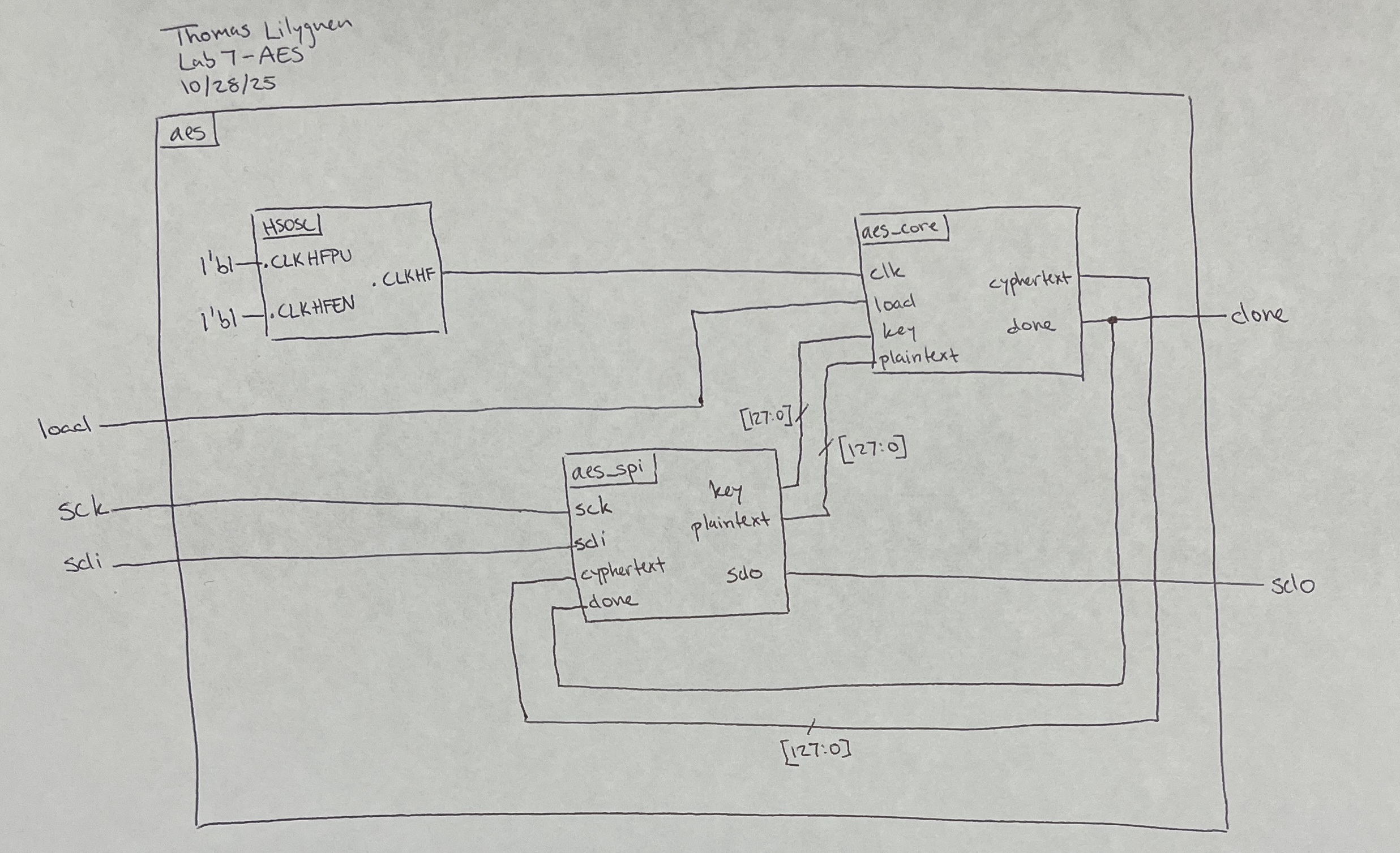
This implementation of AES relied on many levels of abstraction. The top module called on the aes_spi module and the aes_core module. The aes_core function houses all sub-modules present within the AES cycle. The top module, aes_core module, and the FSM state transition diagram are illustrated in Figures 1, 2, and 3, respectively.
Results and Discussion
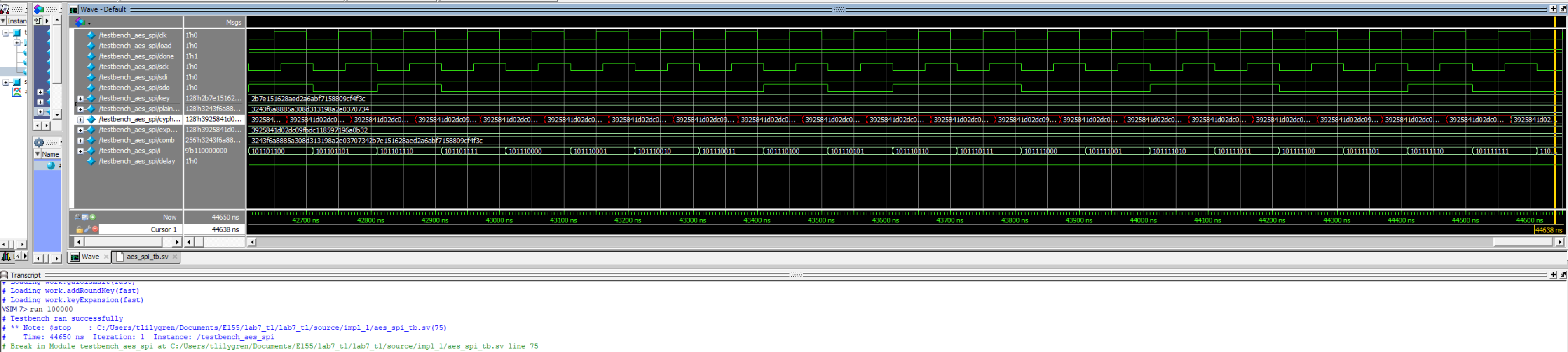
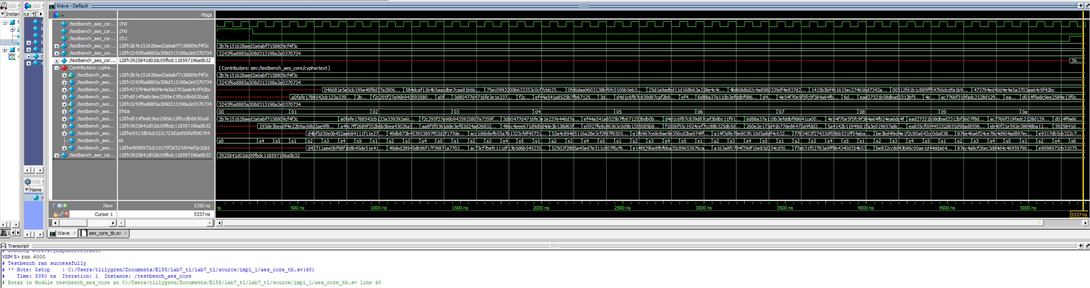
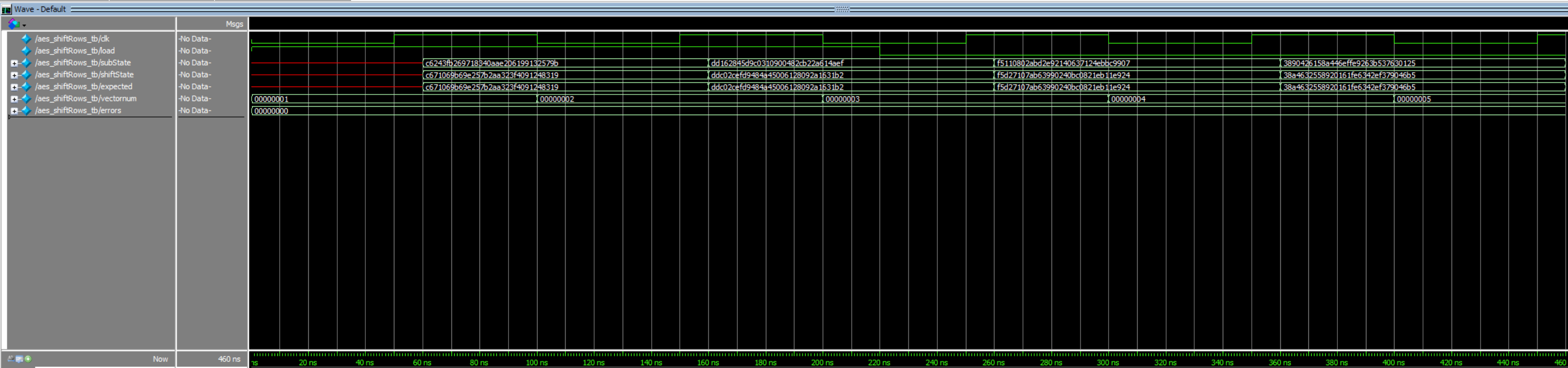
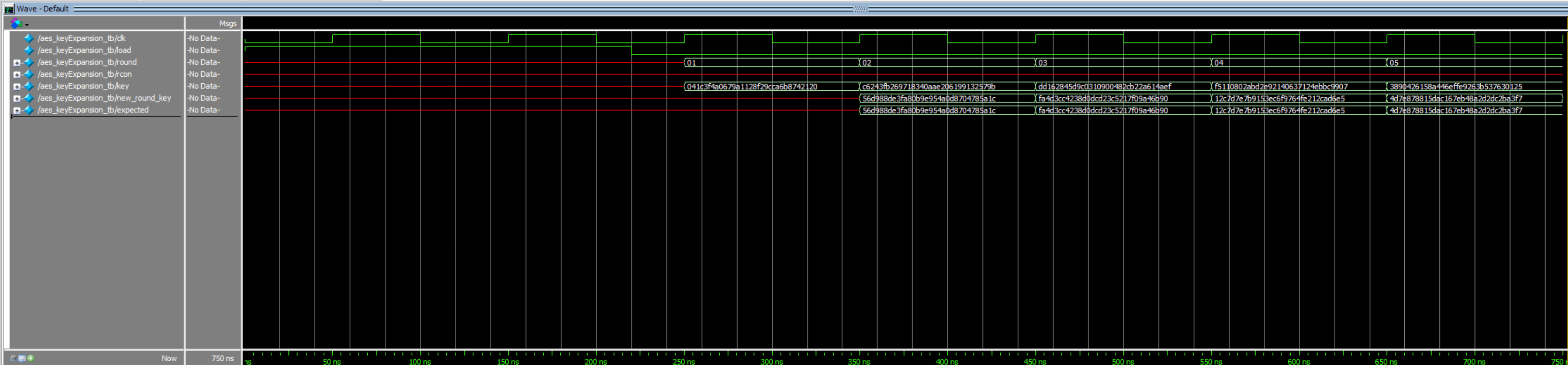
Independent waveforms for each module, and sub-module, by extension, prove proper behavior for the SPI encryption and general message encryption (Figures 4 and 5, respectively). The outputs from these primary aes modules were validated with examples provided in the FIPS 197 appendix, while the building-block modules’ results were validated with personal computation and bit-mapping (Figures 6 through 9). The physical success of this lab was confirmed by measuring the SPI communication with a logic analyzer on the Rigol oscilloscopes provided in lab. The communication patterns were confirmed to match those of the simulation waveforms, indicating that the AES accelerator did not exhaust all FPGA LUTs.
.png)
.png)
Conclusion
After roughly 20-25 productive working hours, this lab meets the listed specifications. The biggest challenge, besides wrapping my head around the lab conceptually, was modifying the aes_core module after running the simulation. The simulation allowed a design with many latches that would disrupt physical implementation. After accounting for these latches, the simulation was executed again and performed as desired.
AI Prototype
As with all other labs, ChatGPT was provided a prompt to see how its performance compares to the hours of hardwork I put into this lab. The first prompt was:
Write SystemVerilog HDL to implement the KeyExpansion logic described in the FIPS-197 uploaded document. The module should be purely combinational, using the previous key and current round number to calculate the next key. Assume other required modules (SubWord and RotWord) are already implemented.
The LLM’s response can be found in Figure 11.
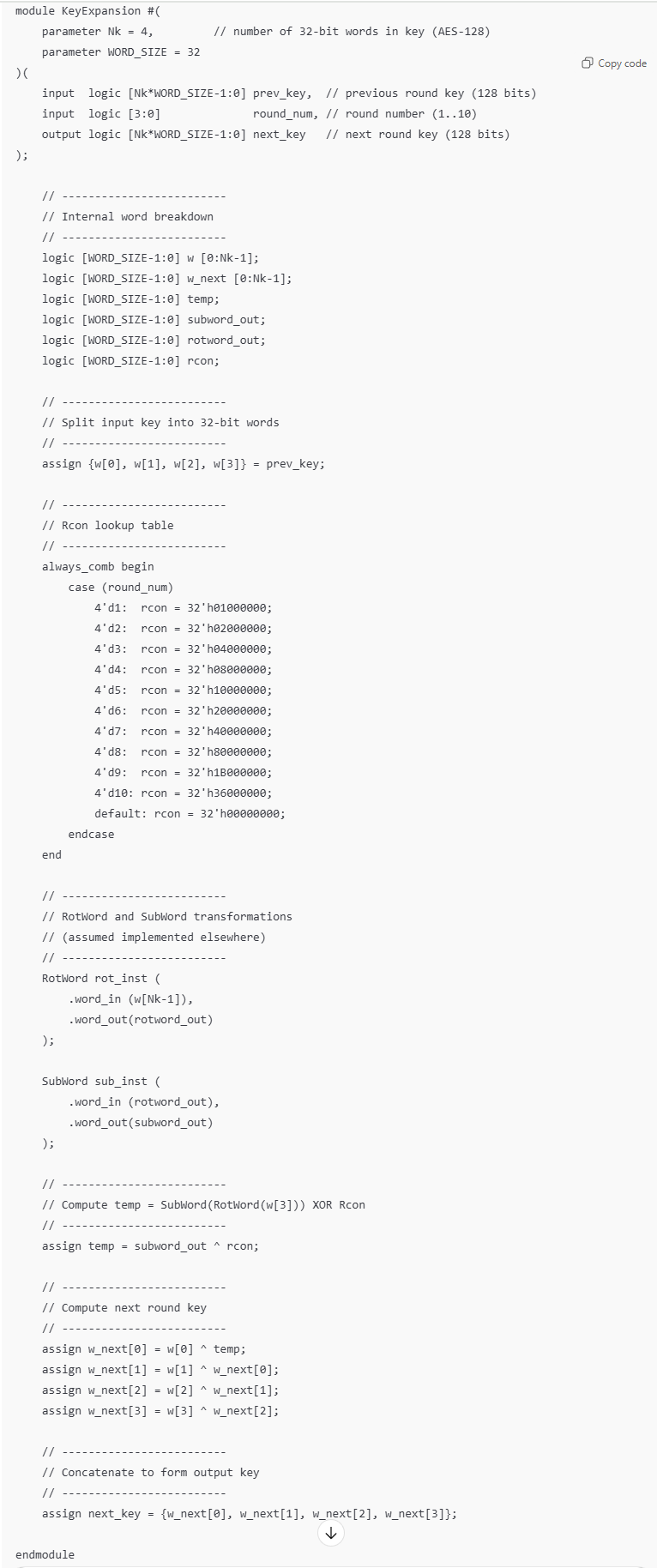
ChatGPT did relatively good job generating the key expansion code. Its use of parameters allows for modular implementation and enhances readability, decreasing the risk of error. The code synthesized properly, only after creating the modules that the prompt referenced. Its code was more readable overall and was separated into manageable sections that would help with debugging.
The AI was tested further by receiving the same pseudocode I had as a reference, from FIPS Figure 5. The response is visible in Figure 12.
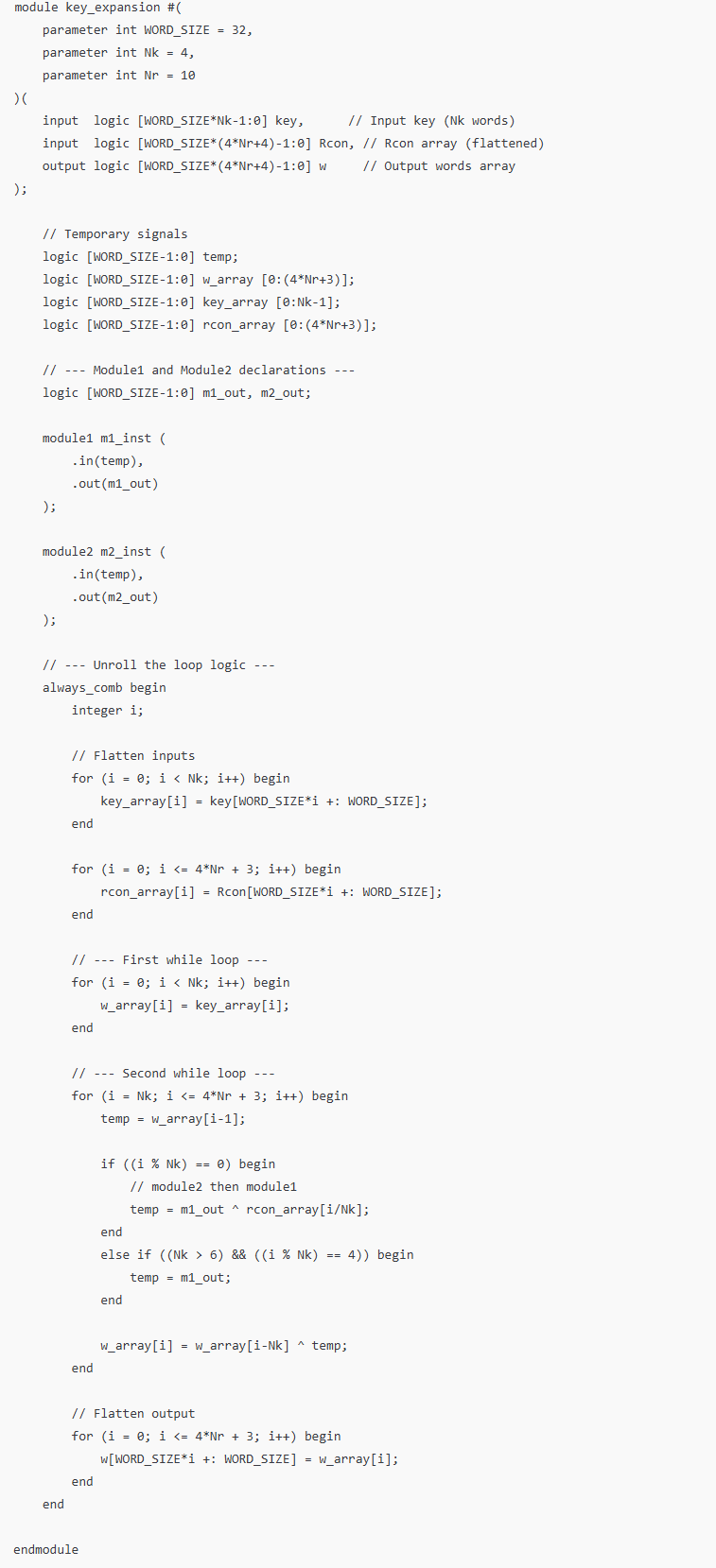
The code when given the second prompt also synthesized once the functions referenced were developed. Regardless, the LLM’s use of for loops in its Verilog code was concerning. While the accuracy and results of its code was not analyzed or tested, I suspect that this would cause issues, especially since it instantiates three separate for loops. I believe that the pseudocode pushed the AI in a different direction compared to when given solely a word-based prompt.