Lab 4: Digital Audio
Introduction
This lab serves as an in-depth introductioin to the STM32L432KCU timer peripherals. Proper configuration of these peripherals allows Fur Elise and Happy Birthday to play based on a set of input frequencies and note durations.
Design and Testing
Timers 15 and 16 were selected to carry out this lab. Timer 15 controls note duration while Timer 16 modulates the frequency for a given input. For both timers, special attention must be paid to the prescalar (PSC) and auto-reload register (ARR) values. The prescalar value divides the 40 MHz input clock and controls measurement resolution, while the auto-reload register value determines the absolute maximum and minimum frequency and duration values that can be achieved at a given prescalar. Both registers for both timers are 16-bits, meaning careful attention must be kept to ensure neither overflows throughout the duration of the songs. For this application, PSC values for both timers were held constant at a value that preserves resolution while modulating the ARR values for the input at a given time. Timer 16 was configured in an alternate mode function for proper GPIO behavior, and the square wave structure relied on the compare-control register to always generate a 50% duty cycle.
Calculations
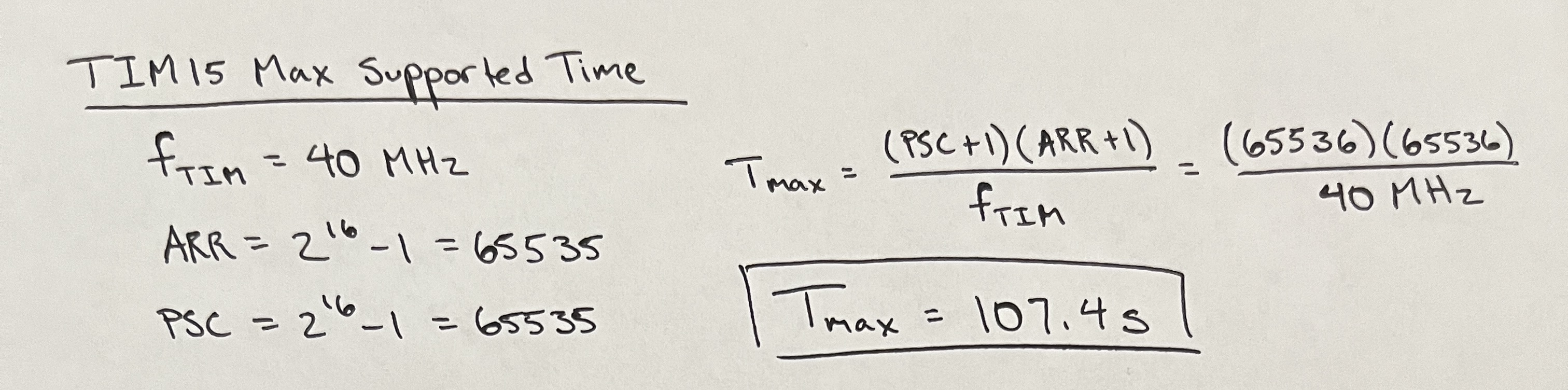
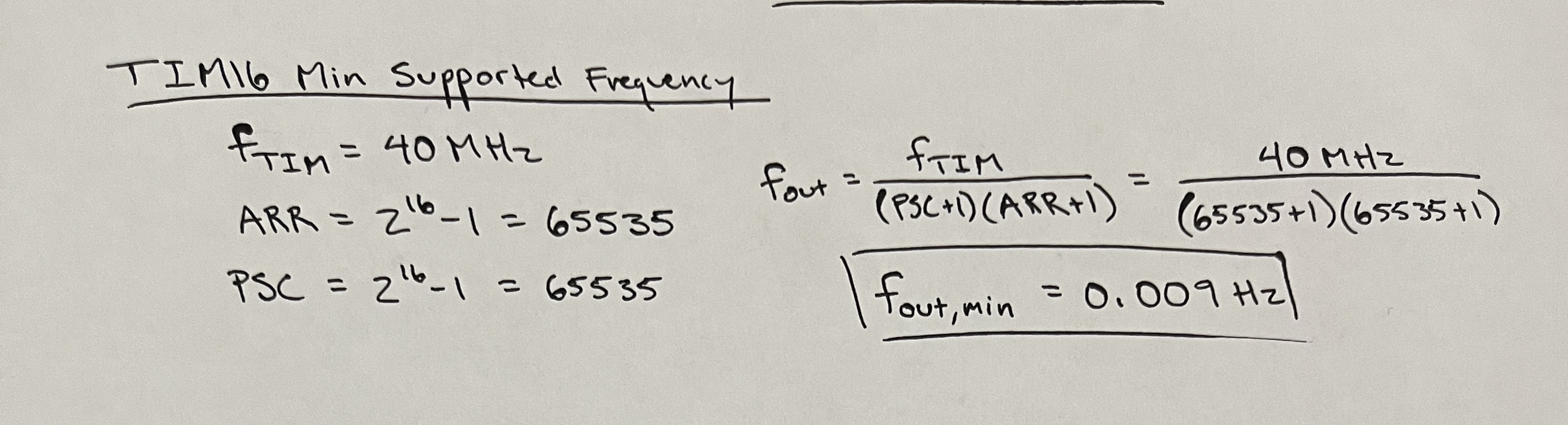
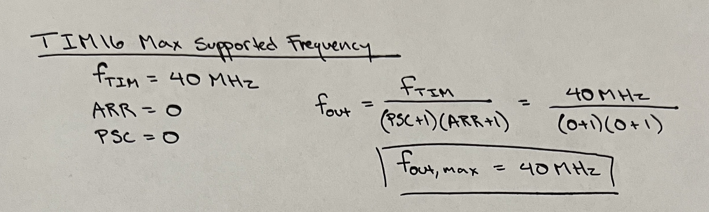
Both timer operated with 16-bit ARR and PSC registers that must be carefully configured to ensure a full range of operability with reliable resolution measurements. Maximizing the ARR and PSC values at 65535 yields the maximum duration the MCU can play a note and the minimum frequency that note could be. By minimizing these values to 0, the minimum note duration and maximum note frequency can be determined. Refer to Figures 1-4 for these calculations.
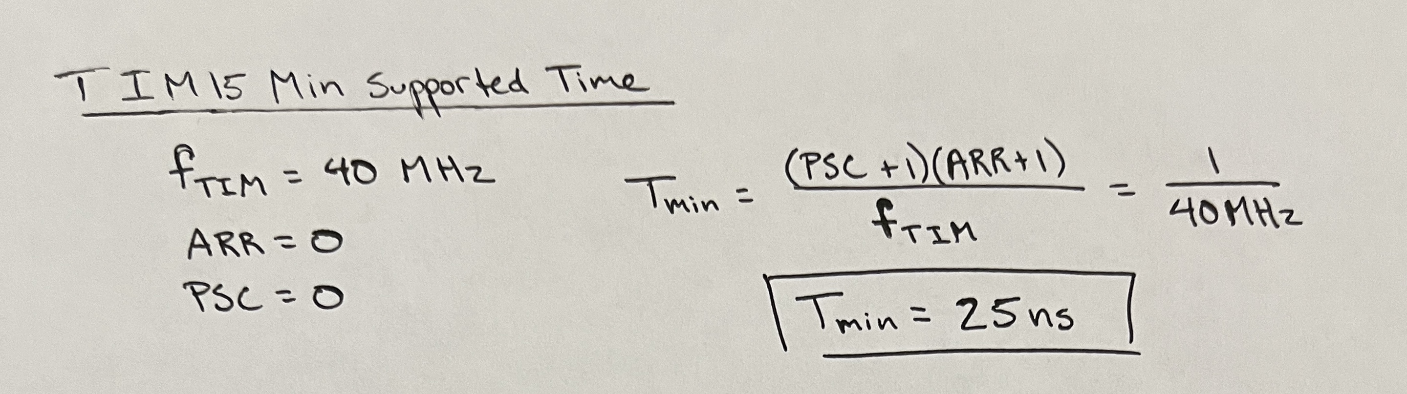
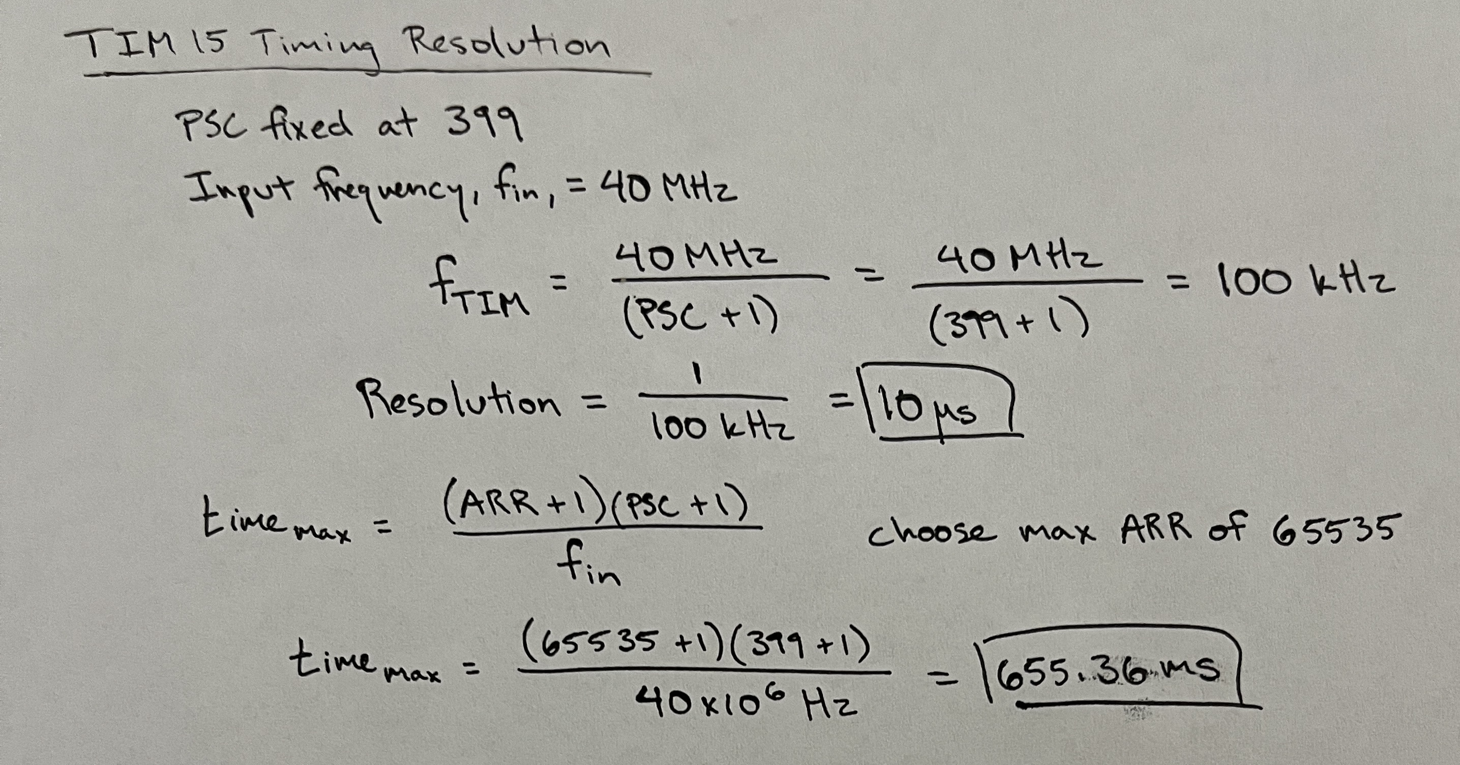
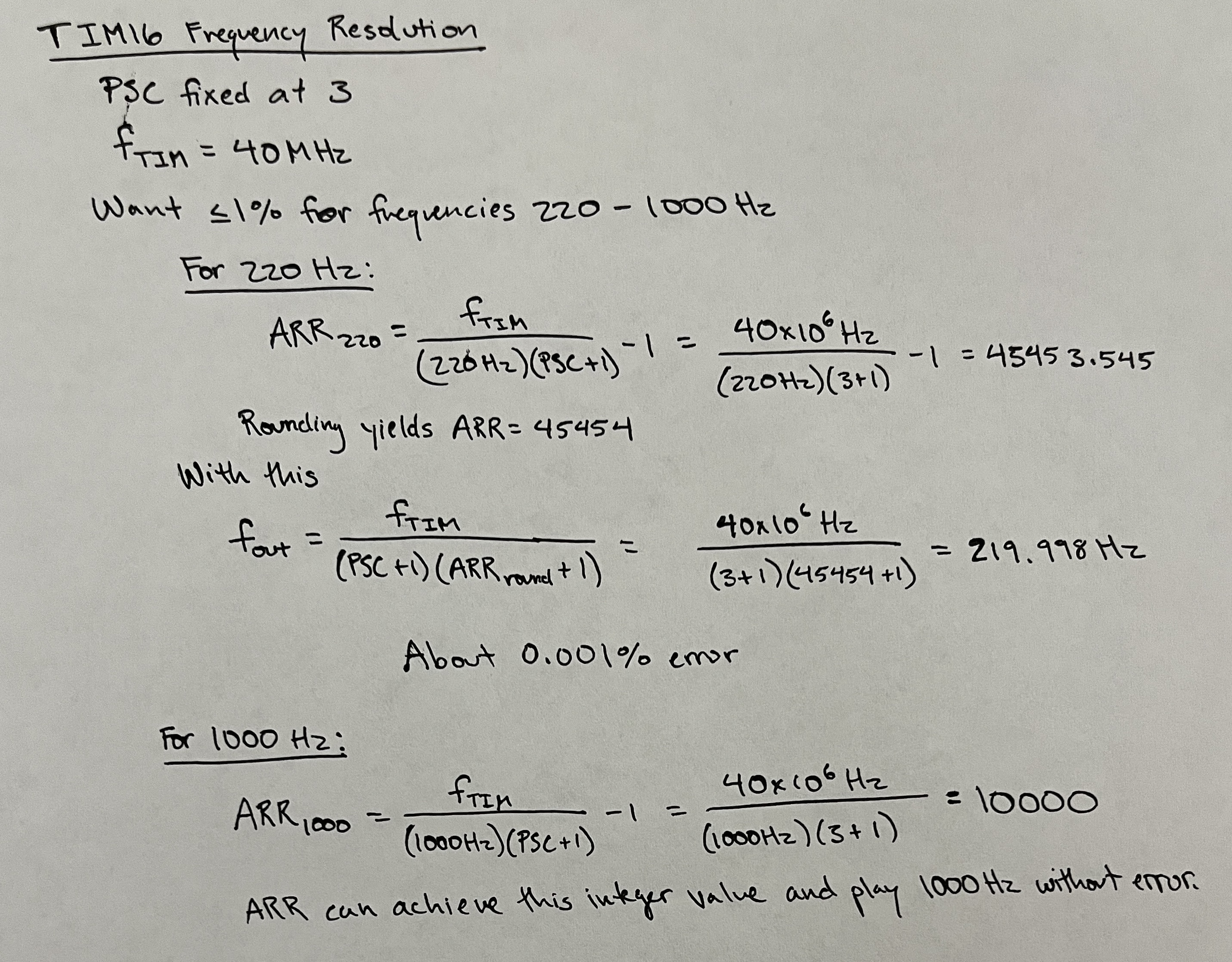
Timer duration resolution can be determined by taking the input frequency of 40 MHz and dividing it by the prescalar. Taking this new frequency and taking its inverse yields the time step between counter ticks. This tick resolution should be capabale of handling minute time changes on the millisecond scale. The frequency output should yield less than 1% error for frequencies between 220 and 1000 Hz. For the preset prescalar, the ARR values for these frequency bounds were determined. Since this value can only be an integer, these values were then rounded and the output frequency for those rounded ARR values were computed. Error for each of these frequencies were well within the 1% error bounds as shown in Figure 6.
Technical Documentation
Electric Schematic
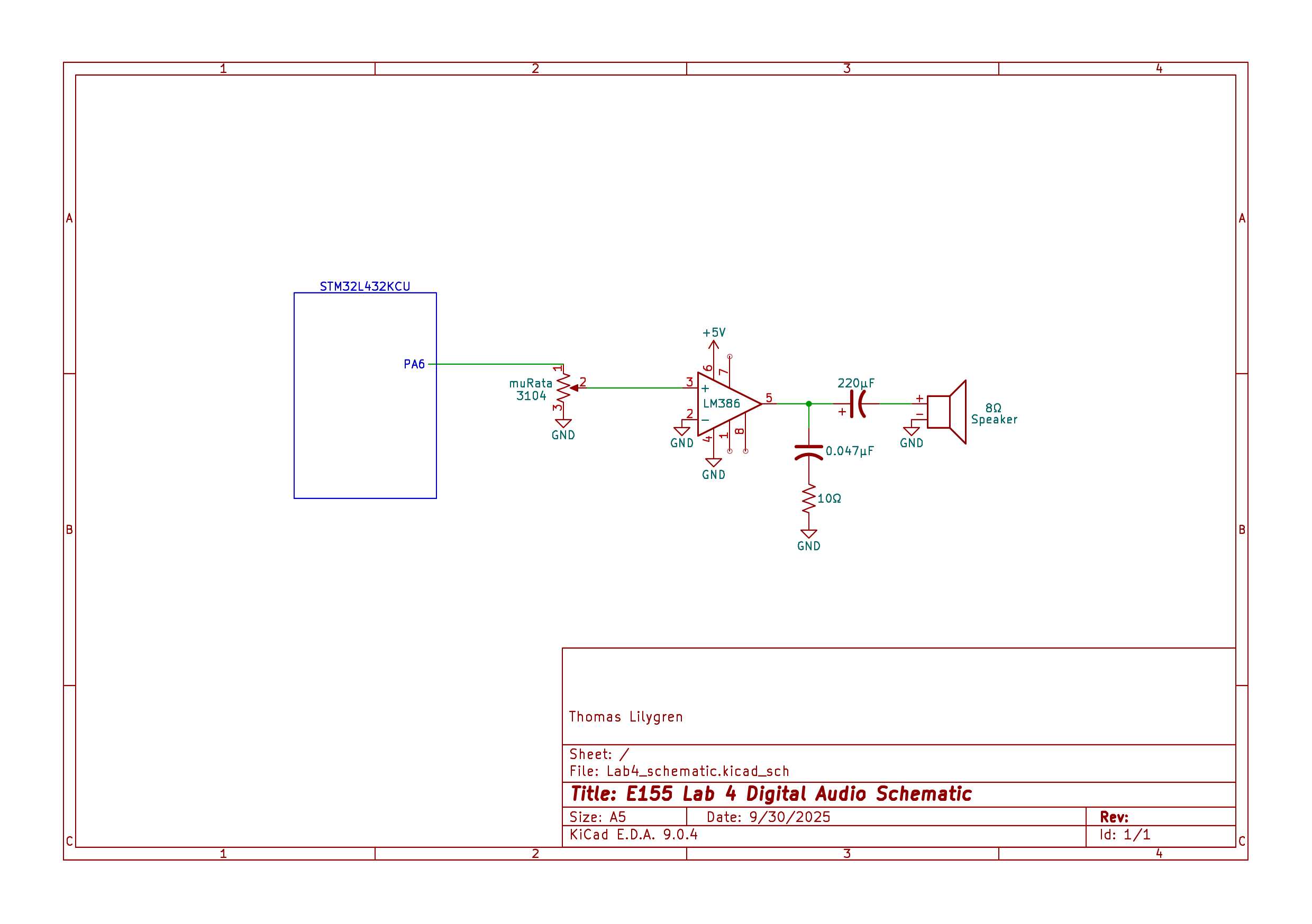
Figure 7 displays the electronic schematic for the entire system. The square wave holding the note was output on the PA6 GPIO pin and fed into a potentiometer for volume control. The output from this potentiometer was fed into the LM386 audio amplifier and the sound was produced with an 8-ohm, 4-Watt speaker.
Results and Discussion
This lab meets all excellence specs, providing proper calculations, clear sound, and multiple songs capable of being played. Successful implementation was confirmed by listening to the sound output and using print debug statements to see if the output frequency and durations matched the inputs.
Conclusion
In all, this lab took about 20 productive hours. Aside from familiarizing myself with the timer registers for proper initialization and duty cycle behavior, the biggest setback was not realizing that the GPIO pins must be configured in alternate mode. Once this was figured out, debugging progressed much faster as I could see where the script was problematic.
AI Prototype
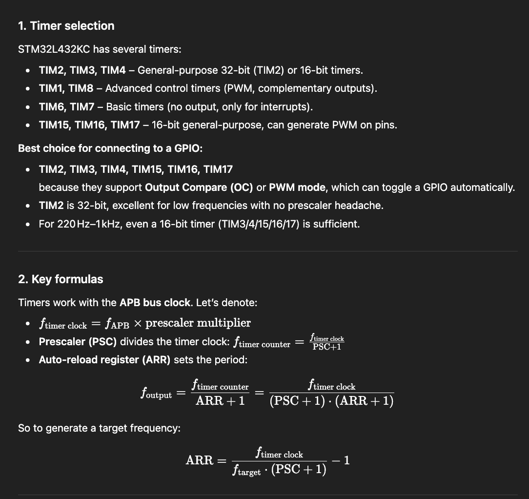
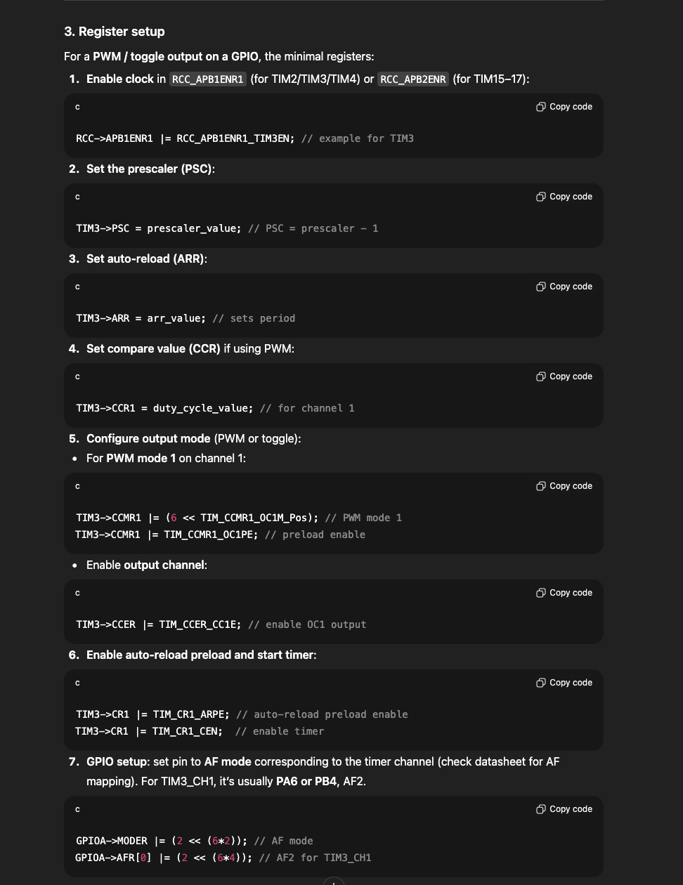
ChatGPT’s capability at setting up this lab was tested by prompting:
What timers should I use on the STM32L432KC to generate frequencies ranging from 220Hz to 1kHz? What’s the best choice of timer if I want to easily connect it to a GPIO pin? What formulae are relevant, and what registers need to be set to configure them properly?
The AI prepared a promising response, providing accurate formulae, configuring registers with CMSIS, and mentioning proper timers. It ends up choosing Timer 3, which is not concerning, but given its configuration with the CCR1 register, it fails to enable proper outputs that would permit sound to play.